The capability extract shows in thirty seconds what runs as standard and what carries a surcharge.
See capabilities →Send the files and an engineer reviews them against your build — free, before you enquire.
To the data check →Rigid zones where components sit, flexible zones where the board has to fold. One part instead of three, no connectors, no assembly step for the cable — and the failure mode that connectors bring with them disappears with them.
Rigid-flex replaces a rigid board, a flat cable and two connectors with a single part. That removes the two most common field failures in a folded assembly at once — the connector contact and the solder joint that holds it — and it removes the assembly step that mates them.
The engineering shifts to the transition zone, where the rigid section ends and the flex begins. That boundary is where nearly every rigid-flex problem originates: a plated hole placed in the bend, a track crossing the transition at a right angle, or a bend radius specified tighter than the material tolerates.
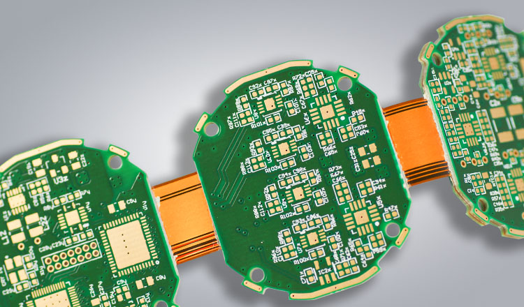
One part instead of board, cable and two connectors. Fewer contact points means fewer field failures and one less assembly operation.
The board follows the enclosure instead of dictating it. In tightly packed devices this is often what makes the mechanical concept work at all.
With rolled annealed copper and a correctly sized radius, the flex zone survives repeated bending — not just the single fold during assembly.
| Feature | Specification |
|---|---|
| Material | FR-4, polyimide, Rogers — bonded rigid and flexible layers |
| Layers | 2 – 12 standard, 13 – 20 advanced |
| Final thickness | 0.3 – 3.0 mm standard, up to 4.0 mm advanced (differs between rigid and flexible zones) |
| Copper | 12 – 105 µm (standard 18 or 35 µm), RA copper in the flex |
| Cover | Polyimide coverlay over the flex, solder mask over the rigid areas |
| Surface finish | ENIG, OSP, immersion silver/tin, lead-free HASL |
| Typical use | Aerospace, medical, wearables, automotive and industrial electronics |
The usual build for this line. Anything outside it is normally still possible — ask and we will confirm.
The flex zone, not the rigid section, sets the limits. Values below apply to the flexible part of the build. Advanced is controlled, but requires a special check before it is confirmed.
| Parameter | Standard | Advanced | Note |
|---|---|---|---|
| Total layers | 2 – 12 | 13 – 20 | Flex layers counted within the total |
| Flex layers | up to 10 | up to 18 | More flex layers stiffen the zone considerably |
| Final thickness | 0.3 – 3.0 mm | 0.3 – 4.0 mm | Differs between rigid and flexible zones |
| Aspect ratio (mech.) | 10 : 1 | 12 : 1 | Board thickness against smallest hole diameter |
| Line / gap (flex) | 100 / 100 µm | 75 / 75 µm | Flex zones tolerate less than rigid sections |
| Bend radius, static | ≥ 6 × t | ≥ 3 × t | Single-sided flex zone; double-sided 7 – 10 × t, multilayer 10 – 15 × t |
| Bend radius, dynamic | ≥ 40 × t | ≥ 20 × t | Requires rolled annealed copper |
| Coverlay | Polyimide 25 µm | Polyimide 12 µm | Adhesive or adhesiveless build |
| Copper (flex) | RA 18 – 35 µm | RA 12 µm | Rolled annealed, not electrodeposited |
| Stiffener | FR-4 / polyimide | Steel / aluminium | For connector and mounting areas |
Guide values for pre-selection. Binding values are confirmed per project against your data.
The points below are what most often comes back as a query after data review. Settling them before layout freeze saves a loop.
A via in the flex area is a crack waiting to happen. Keep all drilled features at least 1 mm clear of where the bend begins.
Tracks should meet the rigid-to-flex boundary perpendicularly and never run diagonally through it. Angled entries concentrate stress on the outer copper edge.
Copper stacked directly above copper stiffens the zone and raises the neutral-axis stress. Offset the tracks between layers so the bend stays compliant.
A one-time fold during assembly and ten million articulation cycles are different products. The copper type, radius and coverlay all change — tell us which one you need.
When the board is bent once during assembly and then stays put. Depth-routed FR-4 costs well below a polyimide rigid-flex build and does the job. As soon as the bend repeats in service, you need real flex.
With rolled annealed copper, a radius of at least twenty times the flex thickness and staggered tracks, dynamic applications in the millions of cycles are routine. Cut the radius in half and the figure drops by roughly an order of magnitude.
Polyimide costs several times what FR-4 does, the panel utilisation is worse because flex outlines nest badly, and the process has more steps. Against that, count the connectors, the cable, the assembly labour and the field returns you no longer have.
On a stiffened area of it, yes — a local FR-4 or polyimide stiffener under the pads makes it possible. On the free-bending part, no.
Send us your data or a rough sketch. We check feasibility, name the cost drivers and answer within one working day.