The capability extract shows in thirty seconds what runs as standard and what carries a surcharge.
See capabilities →Send the files and an engineer reviews them against your build — free, before you enquire.
To the data check →Eleven production lines cover the full spectrum — from a single-sided standard board to HDI with stacked microvias, from a three-day prototype to a flex circuit that replaces a harness. Every line runs through the same certified plants and the same test chain.
Microvias and fine lines pack more interconnect into less space — for compact, high-performance electronics.
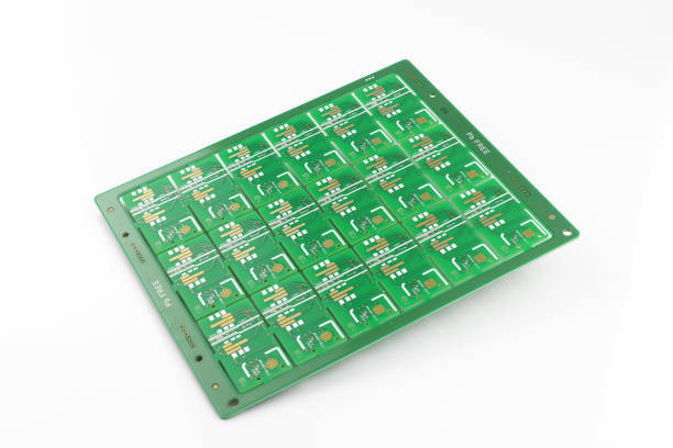
Reliable multi-layer constructions for complex, signal-dense designs with tightly controlled registration.
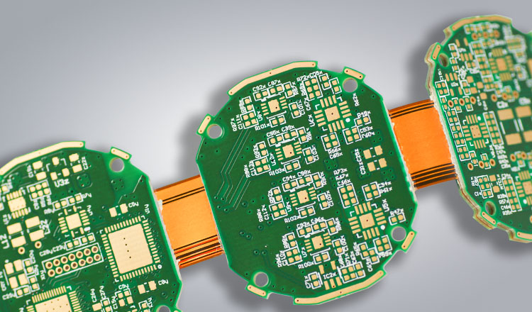
Rigid and flexible zones in one board — no connectors, designed for dynamic bending.
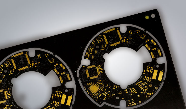
Aluminum-core boards conduct heat away from high-power components — the backbone of LED and power modules.
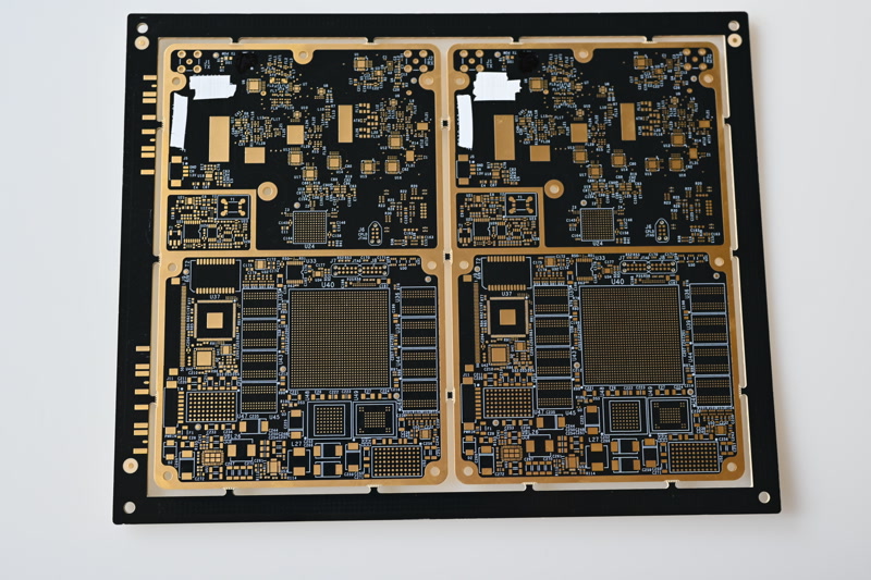
Precise dielectric and trace geometry hold characteristic impedance for high-speed and RF signal integrity.
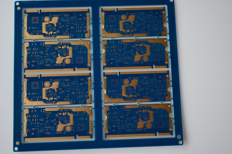
Hard gold-plated edge contacts take the wear of repeated insertion — for connector and card-edge designs.
Copper, steel or aluminium bases for the thermal cases a standard aluminium board no longer covers.
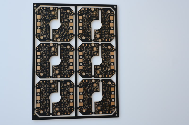
PTFE and ceramic-filled laminates for radar, satellite and mmWave assemblies where loss is the budget.
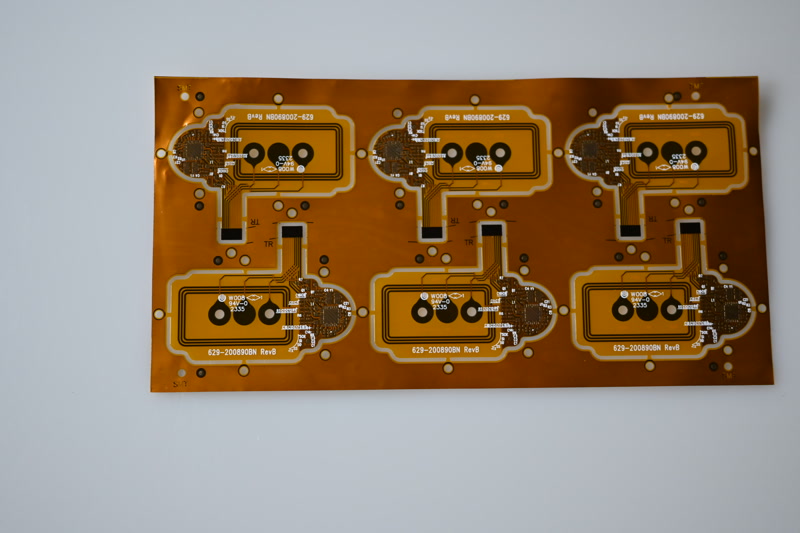
Fully flexible polyimide circuits that fold, route around corners and replace a cable harness outright.
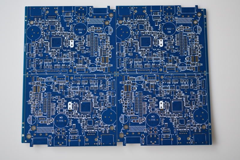
The conventional rigid board — one to twenty layers on FR-4, held to the same process control as everything else.
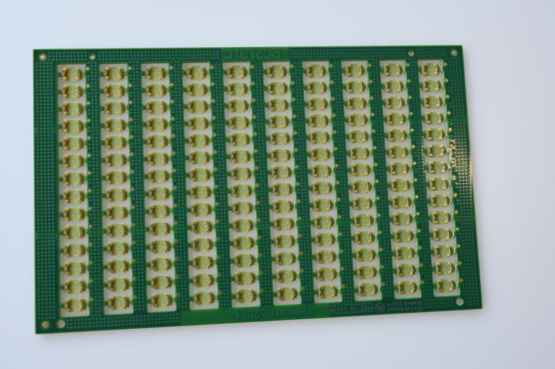
Small quantities on short lead times, built on the same line and the same process that will make the series.
The most common question in a first conversation. This overview answers it in one line per option — including the point most often missed at design stage.
| Line | If you … | Key value | Watch out for |
|---|---|---|---|
| HDI | need very dense packing | 75 µm structure | Fix aspect ratio and microvia stacking early |
| Multi-Layer | route many signals | up to 40+ layers | Build must be symmetrical or it warps |
| Rigid-Flex | want to drop connectors | rigid + flex | No plated hole in the bending zone |
| Aluminum | must dissipate heat | 1 – 3 W/mK | Single-sided assembly, mind the dielectric |
| Impedance Control | run high-speed or RF | ± 10 % | Plan a test coupon in the panel |
| Gold Finger | need insertion cycles | 0.8 – 1.2 µm Au | State bevel and edge clearance |
| Metal Core | need more than aluminium gives | up to 8 W/mK | The dielectric is the bottleneck, not the core |
| Microwave | work above 1 GHz | Df from 0.0009 | Name the laminate grade, not just the brand |
| Flex | want to drop the harness | bends to 6 × t | State static or dynamic before layout |
| Rigid | need a conventional board | 1 – 20+ layers | Give a stack-up, not just a layer count |
| Prototype | need it in days | from 3 days | The clock starts at data approval |
Every limit along the production chain, plus the design notes per chapter.
See capabilities →FR-4 to ceramic — with values and a note on when the switch is worth it.
See materials →Vias, microvia, finishes, heavy copper — the building blocks every line is made of.
See features →Send us your data — we check feasibility and recommend the line that fits technically and makes commercial sense.