The capability extract shows in thirty seconds what runs as standard and what carries a surcharge.
See capabilities →Send the files and an engineer reviews them against your build — free, before you enquire.
To the data check →An aluminium core under a thin dielectric pulls heat out from under the component instead of letting it accumulate in the laminate. For power LEDs and switching stages that is the difference between rated lifetime and early degradation.
A metal-core board — often called IMS, insulated metal substrate — is a simple sandwich: an aluminium plate, a thin thermally conductive dielectric, and a copper layer on top carrying the circuit. Heat travels the short way down through the dielectric into the metal rather than the long way sideways through FR-4.
The dielectric is where the whole design is decided. It has to conduct heat and insulate electrically, and those two demands pull in opposite directions. Thinner conducts better and insulates worse; a higher-filled dielectric conducts better and is more brittle. Which compromise is right depends on the operating voltage and on how much heat the component actually produces.
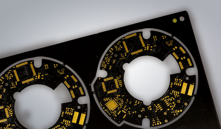
Thermal resistance from junction to core is a fraction of what an FR-4 build achieves. For power LEDs that translates directly into luminous flux held over lifetime.
The metal core makes the board its own heatsink and its own stiffener. In many luminaires it is also the mounting plate, which removes a part from the assembly.
Single-layer aluminium boards are among the cheapest constructions in the portfolio. In LED lighting this is usually the reason they are chosen, not just the thermals.
| Feature | Specification |
|---|---|
| Material | Aluminium core with dielectric layer; FR-4 and polyimide hybrids |
| Layers | 1 – 4 (single-layer is standard, multilayer on request) |
| Final thickness | 0.5 – 2.0 mm |
| Copper | 18 – 105 µm (set by current carrying capacity) |
| Dielectric | 75 – 150 µm, 1.0 – 3.0 W/m·K |
| Surface finish | ENIG, OSP, immersion silver/tin, lead-free HASL |
| Typical use | LED lighting, power electronics, automotive, industrial, telecoms |
The usual build for this line. Anything outside it is normally still possible — ask and we will confirm.
The dielectric determines both thermal performance and isolation voltage. Pick it from the operating voltage first, then check the thermal budget.
| Parameter | Standard | Advanced | Note |
|---|---|---|---|
| Core thickness | 1.0 / 1.5 mm | 2.0 – 3.0 mm | Thicker cores spread heat further sideways |
| Dielectric thickness | 100 µm | 75 µm | Thinner conducts better, isolates less |
| Thermal conductivity | 1.0 – 2.0 W/mK | 3.0 W/mK | Of the dielectric, not of the aluminium |
| Isolation voltage | 3 kV AC | 4.5 kV AC | One minute, to IPC test conditions |
| Copper weight | 35 / 70 µm | 105 – 200 µm | Heavy copper on IMS is possible |
| Line / gap | 150 / 150 µm | 100 / 100 µm | Coarser than FR-4 — the copper is thicker |
| Layers | 1 (single) | 2 – 4 | Multilayer IMS costs considerably more |
| Isolation clearance | ≥ 0.5 mm | ≥ 0.3 mm | Copper to routed edge and to any hole |
Guide values for pre-selection. Binding values are confirmed per project against your data.
The points below are what most often comes back as a query after data review. Settling them before layout freeze saves a loop.
The aluminium is electrically conductive. Every hole and every routed edge needs at least 0.5 mm of isolation clearance, or the circuit shorts to the core.
There is only one copper layer, and the core blocks any through-connection. Anything needing a second side has to become a multilayer IMS, which changes the price bracket.
The dielectric conducts heat but the copper above it spreads it. A generous copper area under the component drops junction temperature more cheaply than a better dielectric does.
Once bent, the dielectric micro-cracks and isolation voltage falls without any visible damage. If the assembly needs a bend, form the aluminium before the circuit goes on.
Aluminium handles the large majority of LED and power applications and costs far less. Copper conducts roughly twice as well and is worth the 60 – 120 % surcharge only when the thermal budget genuinely will not close otherwise.
Not to the core — it is metal. Mounting holes are drilled and left unplated with a clearance ring. If you need through-connections, you need a multilayer IMS build with an insulated via structure.
Most LED work closes comfortably at 1 – 2 W/mK. Going to 3 W/mK helps only when the dielectric is already the dominant term in the thermal path — often it is the copper spreading area or the heatsink interface that limits, not the dielectric.
For LEDs, a white solder mask with immersion silver or ENIG — reflectivity matters as much as solderability. HASL is common on cost-driven single-layer parts but leaves an uneven topography.
Send us your data or a rough sketch. We check feasibility, name the cost drivers and answer within one working day.