The capability extract shows in thirty seconds what runs as standard and what carries a surcharge.
See capabilities →Send the files and an engineer reviews them against your build — free, before you enquire.
To the data check →The board most projects actually need. Nothing exotic about it, and no reason for it to be anything other than exactly right — which is a question of process control, not of technology.
A rigid board is glass-reinforced epoxy with copper on it. That description has not changed in fifty years and it still covers the large majority of electronics built. What has changed is what “standard” means: 100 µm lines, 0.2 mm mechanical vias and ± 10 % impedance are ordinary today and would have been advanced work not long ago.
Because the technology is settled, the differences between suppliers turn up somewhere else — in whether the copper thickness after plating is what the drawing said, whether drill registration holds across the panel, and whether the same board arrives the same way in twelve months. That is the part of a rigid board worth asking about.
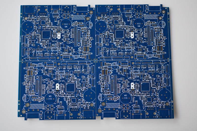
For anything that does not have to bend, dissipate unusual heat, or run above a few GHz, a rigid FR-4 board is the cheapest way to build it and will stay that way.
Standard FR-4, High-Tg for lead-free assembly and thicker stacks, halogen-free where the specification demands it — all through the same process.
The value is in the tolerances holding across a series, not in the headline numbers. Every board runs through the same test chain however simple it is.
| Feature | Specification |
|---|---|
| Material | FR-4, High-Tg FR-4, halogen-free, CEM-1, CEM-3 |
| Layers | 1 – 20+ |
| Final thickness | 0.4 – 3.0 mm |
| Copper | 18 – 105 µm (standard 18 or 35 µm) |
| Surface finish | ENIG, OSP, immersion silver/tin, lead-free HASL |
| Solder mask | Green, blue, red, black, white |
| Legend | White or black, one or both sides |
| Typical use | Consumer, computing, automotive, appliances, industrial electronics |
The usual build for this line. Anything outside it is normally still possible — ask and we will confirm.
Standard runs without a surcharge. Advanced is routine work, but it belongs in the drawing rather than in an assumption.
| Parameter | Standard | Advanced | Note |
|---|---|---|---|
| Layers | 1 – 8 | 10 – 20+ | Above 8 the build must be symmetrical |
| Line / gap | 100 / 100 µm | 75 / 75 µm | 75 / 75 µm verified on 18 and 35 µm copper |
| Mechanical via | 0.30 mm | 0.20 mm | Aspect ratio up to 14:1 at Ø 0.20 mm, 16:1 at Ø 0.25 mm |
| Annular ring | 125 µm | 100 µm | Measured after plating |
| Final thickness | 0.8 – 2.4 mm | 0.4 – 3.0 mm | Thin panels need carriers in assembly |
| Copper | 18 – 70 µm | 105 µm | Heavy copper widens line and gap |
| Outline tolerance | ± 0.15 mm | ± 0.10 mm | Routed; scored edges are wider |
| Impedance | ± 10 % | on review | Defined stack-up and coupon; tighter after technical review |
Guide values for pre-selection. Binding values are confirmed per project against your data.
The points below are what most often comes back as a query after data review. Settling them before layout freeze saves a loop.
“Six layers, 1.6 mm” leaves the dielectric distribution to us. If any signal on the board cares about impedance or crosstalk, the stack-up belongs to the design.
Copper distribution and dielectric thicknesses should mirror around the centre. Asymmetric builds warp during lamination and again during reflow.
HASL is cheapest and unusable below 0.5 mm pitch. ENIG is flat and keeps for a year. OSP is cheap and flat but has a short shelf life and dislikes multiple reflows.
V-scoring is cheaper than routing but works only on continuous straight lines and adds outline tolerance. Anything else has to be routed with tabs.
When it has to bend, when heat cannot get out through the laminate, when a BGA drops below 0.5 mm pitch, or when the loss above a few GHz stops closing. Short of that, rigid is almost always the sensible build.
High-Tg for lead-free assembly, for anything over about eight layers, and wherever the board sees repeated reflow or sustained temperature. The price difference is small and it removes a whole class of delamination risk.
Roughly ± 10 % on final thickness, which is the standard for laminated builds. If a connector or an enclosure needs tighter, say so and we will hold it against a measured value.
Yes. They are still the right answer for simple, cost-driven products, and CEM-1 in particular remains sensible for high-volume consumer work.
Send us your data or a rough sketch. We check feasibility, name the cost drivers and answer within one working day.