EFX 2026 6–8 October, Messe Stuttgart: find us in hall 9, stand C29. Read the post →
Polyimide, bendable

Flex

A flex circuit is a conductor pattern on polyimide that bends. It replaces a cable and two connectors with a single part, which is why it usually wins on reliability before it wins on space.

At a glance
Base film Polyimide, 12.5 – 125 µm
Layers 1 – 6
Copper RA, 12 – 70 µm
Bend radius 6 × t static
Dynamic cycles > 1 million

Flex boards are built on polyimide rather than glass-reinforced epoxy, with rolled-annealed copper that tolerates repeated bending in a way electrodeposited copper does not. A coverlay — a second polyimide film bonded over the traces — takes the place of solder resist, because a printed resist cracks the first time the part is folded.

The main design decision is static or dynamic. A static flex is folded once at assembly and then left alone: it can be thicker, carry more layers and use a tighter radius. A dynamic flex bends repeatedly in service and constrains almost everything — single-layer where possible, copper on the neutral axis, generous radii, and no plated hole anywhere near the bend.
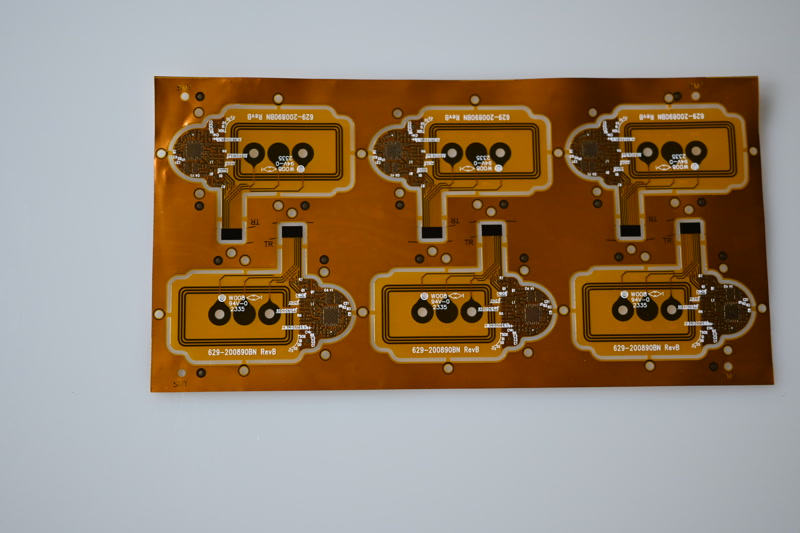
Flex

What it delivers

[ Overview ]
01

Replaces the harness

One flex circuit instead of a cable, two connectors and two crimps. Fewer parts, fewer joints, and the assembly cannot be plugged in the wrong way round.

02

Fits where nothing else does

It folds into the space that is left rather than demanding a space of its own. In handhelds and instruments that is usually the whole reason.

03

Survives movement

Rolled-annealed copper on the neutral axis takes millions of cycles. A wire harness in the same place fatigues at the strain relief.

Build and options

[ Datasheet ]
Feature Specification
Base film Polyimide, 12.5 – 125 µm
Layers 1 – 6 (single and double-sided are standard)
Copper Rolled-annealed, 12 – 70 µm
Coverlay Polyimide with acrylic adhesive, 12.5 – 25 µm
Stiffener FR-4, polyimide or steel, under connectors and components
Final thickness 0.10 – 0.40 mm in the flexible area
Surface finish ENIG, OSP, immersion tin — ENIG standard
Typical use Wearables, cameras, medical devices, instruments, automotive displays

The usual build for this line. Anything outside it is normally still possible — ask and we will confirm.

Flex limits

[ Specification ]

Static and dynamic are two different specifications. The dynamic column below assumes single-layer with the copper on the neutral axis.

Parameter Standard Advanced Note
Layers 1 – 2 4 – 6 Every added layer raises the minimum bend radius
Bend radius, static 10 × t 6 × t Measured to the inner surface
Bend radius, dynamic 100 × t 50 × t Single-layer only, copper on the neutral axis
Line / gap 100 / 100 µm 75 / 75 µm Etch tolerance is wider than on rigid
Copper 18 – 35 µm 12 or 70 µm RA copper for anything that actually flexes
Base film 25 µm 12.5 µm Thinner film bends better and handles worse
Hole diameter 0.30 mm 0.20 mm With an annular ring on both sides
Stiffener FR-4 Steel Under connectors and every soldered part

Guide values for pre-selection. Binding values are confirmed per project against your data.

Typical applications

[ Use cases ]
Wearables and body-worn monitors
Camera and display module interconnects
Endoscope and catheter electronics
Folding and hinged consumer devices
Instrument head-to-body interconnects
Automotive display and lighting harness replacement

Design rules

[ Layout ]

The points below are what most often comes back as a query after data review. Settling them before layout freeze saves a loop.

01

Never put a plated hole in the bending zone

A via in a bend is a stress concentrator and a guaranteed crack. Keep every hole, pad and stiffener edge at least 1 mm clear of the flexing area.

02

Route traces perpendicular to the bend

Traces should cross the bend line at right angles and stay evenly distributed across the width. Traces that run along the bend, or cluster on one edge, tear first.

03

Use curves, not corners

Sharp corners in the outline or in a trace concentrate strain. Fillet the outline and radius every change of trace direction.

04

State static or dynamic in the drawing

The two have different copper, different layer counts and radii that differ by an order of magnitude. It is the first thing we need to know and the most common omission.

Frequently asked

[ FAQ ]
Flex or rigid-flex?

A flex plus connectors is cheaper per part; a rigid-flex removes the connectors and is more reliable. If the rigid ends are simple and the volume is low, flex with connectors usually wins. Once the connector count or the vibration environment rises, rigid-flex pays back.

How tight can I bend it?

For a static single fold, roughly six times the total thickness to the inner radius. For dynamic flexing, fifty to a hundred times, single-layer, with the copper on the neutral axis. Anything tighter needs a discussion before layout.

Can I put components on a flex?

Yes, but not in the flexing area, and every soldered part needs a stiffener underneath. Without one, the reflow and the first flex both work against the joint.

Why rolled-annealed copper?

Electrodeposited copper has a columnar grain structure that cracks under repeated bending. RA copper has elongated grains in the plane of the sheet and takes orders of magnitude more cycles.

Related

[ Cross-reference ]

Does this fit your project?

Send us your data or a rough sketch. We check feasibility, name the cost drivers and answer within one working day.